
Pseudo Random Code (PRC) ionosondes
The ionosonde for the oblique sounding that will be used in the Iononet project is a coded continuous wave ionosonde, which utilizes long Pseudo-Random Coded transmit waveforms (PRC radar). The random code in the transmitted signal allows us to distinguish among signals transmitted from different sites of a multi-static cooperative radar network. A similar approach is used by the global positioning system (GPS) where a single GPS receiver can use the radar signals of several satellites at the same time, with the particularity that the transmitter's start time is coded in the signals. PRC radars have several advantages: they can be used at low peak power, can measure range or velocity (using Doppler effect) over spread targets, they are relatively robust against external interference and they produce relatively low interference to other users that share the same portion of the electromagnetic spectrum. Moreover the low cross-correlation between coded signals from different transmitting stations allow to transmit, receive and elaborate the different received signals at the same time. This ionosonde design is thus well suited for use in ionosonde networks [Floer, 2020].
The waveform generated by the PRC ionosonde is built on the base of a set of parameters included in the configuration files (*.ini); in the following the parameter names will be enclosed in square brackets. We start from a sequence of random numbers that will define the phase values of the transmitted wave, after the formula: . The function rnd is a typical one that generates pseudo-random numbers, it is based on a seed specified by the parameter [stationid] that is equal to the code that identifies the transmitting station; in this way each receiving station is able to extract from the received signal only the sequence generated by the transmitter to be decoded. The sequence is made up by [codelen] values, this sequence might be longer than the one that will be actually transmitted, being this length fixed by the parameters [pulselength] and [ipp] that specifies the length of the pulse and of the transmission, respectively; this double specification was introduced to allow the possibility of transmitting a sequence of pulses or a continuous wave. If [pulselenght] ³ [ipp] only the first code values until [ipp] will be transmitted. If [pulselenght] < [ipp] after the first [pulselenght] values, the transmitted sequence goes on until [ipp] filling the values with zeroes (see fig. where [pulselenght]=200 and [ipp]=400). When all the values till [ipp] are sent, the sequence starts again.
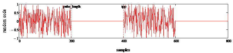
Coded pulse example in the case of pulsed signal.
The same result of putting [pulselenght] = [ipp] can be achieved by placing [pulselenght] = ‑1; in this way the system recognizes that must send a continuous wave. There is a parameter [dec] that specify an oversample, so that every value of the sequence is repeated [dec] times; therefore, the same value will be received [dec] times (plus noise) and averaged, increasing the signal-to-noise ratio. The parameter [samplerate] sets the sampling frequency, its reciprocal being the time interval between two samples; as a consequence, the value D = [ipp] x [dec] / [samplerate] is the duration in seconds of the sequence of values actually to be transmitted. All the sequence is used to modulate a carrier at a single frequency, being its module equal to one and the phase calculated after the formula defined above. There is a last parameter [frequencyduration] that sets the transmission time at a single frequency. After the time [frequencyduration] expires, a new sequence is generated and transmitted using a different carrier frequency. Starting from 1 MHz, with 0.1 MHz steps, there are 240 different values, being the last one 25 MHz. The typical values used for the ionosonde parameters are:
[codelen] = 10’000
[dec] = 10, so there are 100’000 total values
[pulselenght] = -1, so a continuous wave is generated along D duration
[samplerate] = 1, means 1 MHz, so the sample interval is 1 μs, and D = 0.1 s
[frequencyduration] = 1s;
therefore, the sequence is repeated 10 times at the same frequency before passing to another frequency. The whole sounding lasts 4 minutes; it is repeated 15 times in an hour without breaks. The soundings start at minute 00 of each hour; to avoid loss of synchronisation between the transmitter and the receiver, GPSDO are used (with accuracy of about some nanoseconds). As said, the ionogram duration takes 4 minutes, this choice allows to study the ionosphere dynamics and changes. A longer duration could measure a changing ionosphere (not coherent measurements), while a lower duration with a shorter code reduces the signal process gain useful in long distance connections with greater geometrical attenuations.
Oblique Ionosonde Characteristics :
Sounded frequencies 1 - 24.9 MHz
Frequency resolution 0,1 MHz
Sounding time per frequency 1s
Number of traces 240
Total sounding time 240 s (4 min)
Vertical resolution 1,5 km
Numbers of vertical points 1'000
height range 0 - 1500 km
Sample frequency 1 MHz
Number of acquired samples per trace 1 MSmp
Decimation factor 10
Number of samples per trace 100 kSmp
Number of point in receiver data file 240 x 100'000
Bandwidth 100 kHz
Code len 10'000 pseudo random sample
Number of trasmitted pulses 10 per sounded frequency