
Measurement Techniques
Vertical surveys of the ionosphere are based on the use of HF radars, ionosondes, in which TX and RX antennas are located. Vertical ionosondes are the main tool for mapping the ionosphere locally for the verification of theoretical models of the global ionosphere and to study the possibility of using local variations in electron density also as possible precursors of earthquakes.
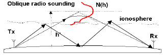
Oblique surveys involve the placement of TX and RX antennas in different locations, even thousands of kilometers away.
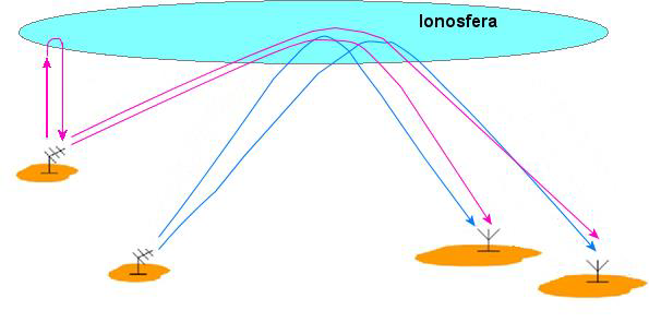
Using several transmitting ionosondes to receive there are two possible configurations of the transmissions, one is the use of different time slots for each transmitter (transmitting at different times) or coding the transmitting signals in such a way to be recognized and discriminated by the receiving ionosondes.
The first method reduces the number of soundings, waiting the four transmission time at each receiver, while in the second method can make four sounding at the same time at each receiver but with a more complicated random coded transmission system.
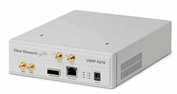
Moreover, the use of SDR devices help to resolve complicated RF systems thanks to their programmability. SDRs are very adaptive devices that can be programmed by software writeen in Python or C++ and connect to a PC through a fast Ethernet line (RJ48) or USB for configuration and data transmission.
Classic ionosondes are pulsed radar that, emitting a sequence of radio frequency pulses and measuring the delay time between the transmitted pulse and the received one, makes it possible to obtain the distance of a "target", i.e. a reflector, hit by the transmitted impulse, knowing the speed of propagation of the wave in the medium. This radar technique is used in ionosondes to measure the height of the reflecting layers of the ionosphere [Arokiasamy et al. 2002]. In vertical surveys, the transmitter and receiver are placed in the same observation point (monostatic radar). However, this causes a problem for the receiver during the transmission of the impulse, because it is directly hit by the transmitted high-power signal, which can create problems of saturation or even failure of the first stages of the receiver; therefore, it is turned off for the entire duration of the transmission impulse (“blind time”). In oblique surveys (bistatic radar), since the transmitter and receiver are located in places separated by hundreds or thousands of kilometres, this problem does not arise, therefore different techniques as in our case, continuous wave (CW) radar can also be easily used [Farnett et al. 1990, Alter et al. 2008]. However, the bistatic technique, used over large distances, requires time synchronization of the transmitted and received signal for the exact determination of the arrival time of the echo. In this case, it is possible to use time synchronization techniques with GPS (Global Positioning System) systems, which allow synchronizing two devices located at a great distance with errors less than a microsecond. Moreover, through GPSDO (Disciplined Oscillator GPS) techniques it is possible to synchronize the phases of the signals of transmitter-to-receiver reference oscillators with very small phase errors.